
Why does LAoE use 5% resistors when 1% costs the same?
All electronic components have tolerance — the maximum deviation you can expect around its nominal value. When I started in electronics, the cheapest resistors were carbon comp[osition] spec’ed at +/-20%, meaning a 1K resistor could be anywhere between 800 Ohms and 1.2K. Over time, as manufacturing process improved, 20% and 10% resistors gave way to 5% as the standard tolerance, with 1% resistors costing more. Nowadays, 5% resistors are less common since 1% resistors are no more expensive.
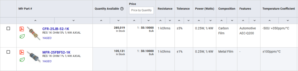
A search for a 1K, 1/4W resistor at DigiKey shows identical pricing.
Not only does the 1% resistor cost the same as the 5% part, it is more accurate and has a lower temperature coefficient.[1] So why does Learning the Art of Electronics insist on using 5% resistors (except for the instrumentation amplifier in lab 7L.4)?
The answer is pedagogical. Our goal in LAoE is to give you a firm foundation in electronic circuit design to allow you to create your own projects in the future. One of the issues you need to consider when designing circuits is how important is the tolerance of a component. Sometimes the actual value of a resistor is relatively unimportant (say when used as a pullup as in Figure 16L.6). In other cases the tolerance matters, such as in an RC oscillator; see lab 8L.5. If we let you use 1% resistors in the LAoE labs, you would rarely have to even think about tolerance — but we want you to start building good design habits now.
In addition, standard resistor values are designed to have the upper tolerance of the lower value just meet the lower tolerance of the next higher value. Thus standard 5% values go in a 1.0, 1.1, 1.2, 1.3, 1.5, etc. sequence of 24 values per decade while there are 96 values per decade for the standard 1% resistors. Since you are less likely to have the exact 5% value you want when you calculate the value for a voltage divider or an RC oscillator, we want you to get used to deciding how important an exact value is. If you need a more exact value you need to use a 1% (or even tighter tolerance) resistor. Judgement is an important skill in creating good circuits.[2]
[1] Temperature coefficient is the change in a component’s value with a change in temperature. In a high precision application, a device or circuit may be placed in a temperature stabilized enclosure (an “oven”) to minimize variation with environmental temperature. This technique is often used in precision crystal oscillators. See e.g., https://en.wikipedia.org/wiki/Crystal_oven
[2] In our class, students invariably want to create a more exact value by paralleling or using a series connection of two 5% values. We warn students that is is not acceptable. If they need a more exact value they should use a 1% resistor, but the experiments in the book (with the exception of the instrumentation amplifier) are designed for 5% values, so you should not need any other 1% values.
Read MoreA breakout board for a small surface mount component
While looking for a charge pump (a circuit to create a negative voltage from a positive source for low current applications) I discovered the Analog Devices LTC3261 High Voltage, Low Quiescent Current Inverting Charge Pump. Unfortunately, this device only is available in a very tiny 12-pin MSOP surface mount package. I decided to design a breakout board so I could use the LTC3261 with our standard plastic breadboards.
I have documented the process of designing and having this breakout board manufactured, including the [free] printed circuit design tool I used, where I had the printed circuit board (PCB) made, how I soldered the surface mount devices (SMD) to the PCB, and the tools I use to verify the value of two-terminal SMD devices.
This discussion is at Designing a breakout board for the LTC3261 charge pump.
Read MoreA reader asked “If you mean R1, why not just say R1?”
Section 4W.2 of Learning the Art of Electronics walks the reader through the design of a single bipolar transistor phase splitter, a circuit that splits an input into two waveforms, 180° out of phase with each other. After choosing the emitter and collector resistors to set the each output’s quiescent value to get the maximum output swing with an anticipated 1mA of quiescent collector current, the example addresses the bias divider. The circuit at this point looks like this:
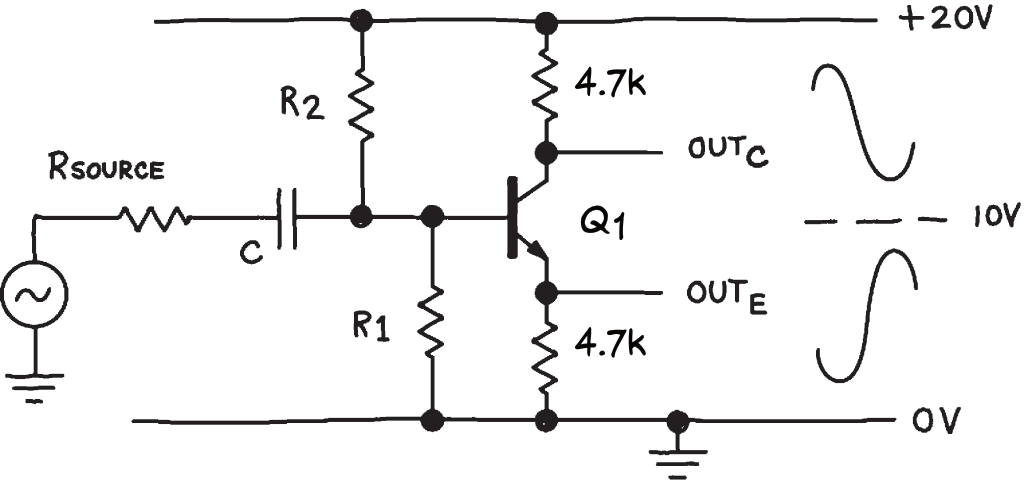
4W.2 Phaser splitter worked example before bias divider calculations
We need to set the voltage at the base of Q1 at ~5V to get the 1mA of quiescent collector current, so the ratio of R2:R1 should be 3:1. The reader asked why in the calculation of the resistor values we use “R” rather than “R1” if we are calculating the value of R1?
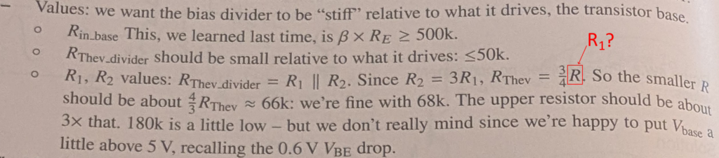
LAoE page 192 calculation of base bias resistive divider for phase splitter
The use of R rather than R1 in the formula for RThev and the description “the smaller R” rather than R1 is deliberate. R1 is only the smaller resistor in this circuit when Q1 is a NPN BJT. You could just as easily build this circuit with a PNP device and it would work as well but then R2 would be the smaller resistor. (Of course the in-phase and out of phase outputs would be reversed with the PNP.)
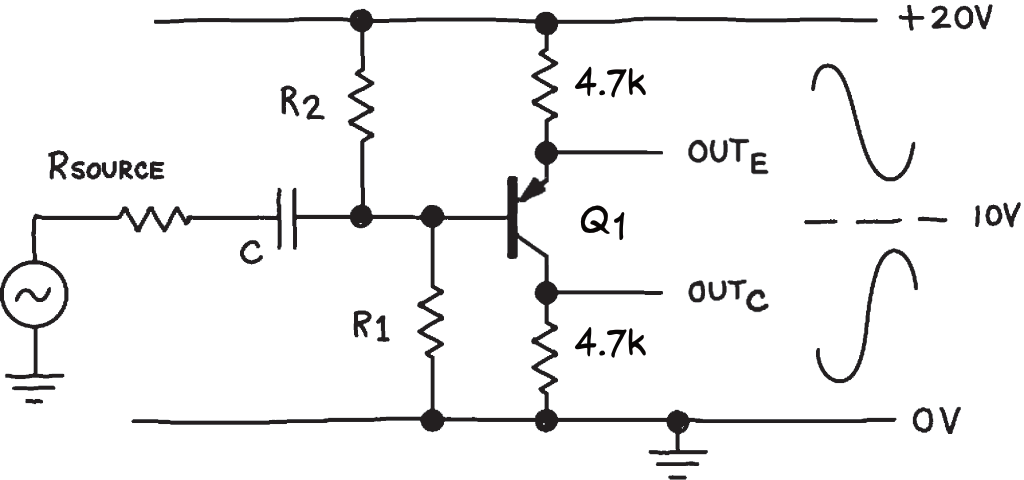
The phase splitter of worked example 4W.2 using a PNP transistor.
In this version, the formula for the Thevenin equivalent resistance of the divider is unchanged but R2 is the smaller resistor. The design description is trying to be non-denominational so you don’t think you need a different calculation for the PNP version.
Read MoreSave $12 and learn more by building your own LT1073
Section 12L.2 invites readers of Learning the Art of Electronics to build both a boost (output voltage higher than input) and buck (output voltage is lower) switching voltage regulator using an LT1073 micropower DC-DC Converter. If you ever need a buck or boost converter in a project, the LT1073 and its sibling the LT1173 are wonderful devices. In the fixed-voltage version, you need only add an inductor, a diode, and a capacitor to the 8-pin DIP to get up to 40mA at 5V from a 1.25V source. In LAoE we use the adjustable version of the LT1073 which adds two resistors to allows us to set the output voltage to a value other than 5V or 12V. Unfortunately, the LT1073 is moderately expensive (USD$ 10.72 as of 5/2026). In addition, it hides the workings of a switching voltage converter. This is fine if you need one for a project but less ideal as a teaching exercise.
Luckily, by Chapter 11 LAoE readers have been introduced to almost all of the circuits in the blocks inside the LT1073. This means you can build the circuits in lab 11L.2 with parts you have already used (plus a MOSFET transistor on the analog parts list) and see how they go together to create a switching voltage regulator. Here is an annotated version of the block diagram of the LT1073 showing discrete replacements for the circuits inside the device.
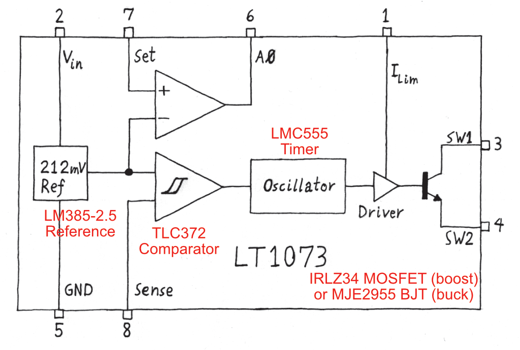
Annotated LT1073 block diagram showing the discrete circuits used to replace the device’s internal blocks. We don’t include the x1000 amplifier optionally used to reduce ripple in Figure 11L.13 but you could use a LMC6482 to replace it as well.
By building the circuits of 11L.2 out of separate components, you also gain the ability to look at the inputs and outputs of each of these blocks, something not possible with the integrated device.
See Substitute for the LT1073 regulator on the analog parts list for complete directions on completing lab 11L.2 without the LT1073.
Read MoreA replacement for the SparkFun SerLCD display
A reader wrote:
You may need to suggest an alternative to Sparkfun 16×2 LCD Display because it costs $32.50 currently. There are many 16×2 LCDs around that cost about $3, what makes Sparkfun special?
I responded:
Unfortunately, replacing the SparkFun display it is not as simple as buying a inexpensive 16×2 line LCD from Alibaba (https://www.alibaba.com/product-detail/1602-Yellow-Backlight-STN-LCD-Module_62296368457.html) for USD $3.
The SparkFun display is used to demonstrate how to use the SAMD21 SERCOM peripheral which supports several serial data transfer protocols. The cheap LCD character displays you reference use a parallel (4 or 8 line) interface. (Dot matrix LCD displays usually do support a serial protocol, either SPI or I2C, but the software to display two lines of text on them is much more complicated than we have room in the book to explain.) The SparkFun display supports all three common serial protocols, UART, I2C, and SPI. We use the latter in the book to drive the display.
It looks like Amazon currently (4/2026) has the SparkFun display for slightly less than buying direct: $USD 26.50 at https://www.amazon.com/SparkFun-16×2-SerLCD-Compatible-Communicate/dp/B08H9W2R1D/ saving about USD$ 6.
I now have spent some time looking at alternatives and came up with several solutions which vary in cost, effort to put together, and fidelity to the SparkFun SerLCD. See Substitutes for the SparkFun SerLCD Display
Read MoreConsider kits instead of individual components
I recently finished building a high-voltage power supply for my home lab and needed a number of new parts I did not already have on hand. Many of the parts I ordered from Mouser and Digikey including the LR8 voltage regulators, high-voltage MOFETs, the heat sinks, several high-voltage capacitors, and 100 1N4007 rectifier diodes. [1] However, there are often parts where I am unsure of what value I will need or that I might use similar but not identical parts in future projects. For this latter category of items a kit of parts might make more sense because I can get an assortment of similar items at a relatively small cost to test in my circuit and stock in my lab.
For example, for the high-voltage power supply I was unsure if a linear or logarithmic potentiometer would give a more natural feel for adjusting the voltage. Rather than buy a few select values, I found this potentiometer assortment for $26 that pretty much covers any one-turn pot I would ever need. In addition, distributors like Digikey and Mouser require you to buy the potentiometer and knob separately, whereas the kit includes both (as well as washers, nuts and dust seals). It even includes a nut driver to tighten the potentiometer to a panel.
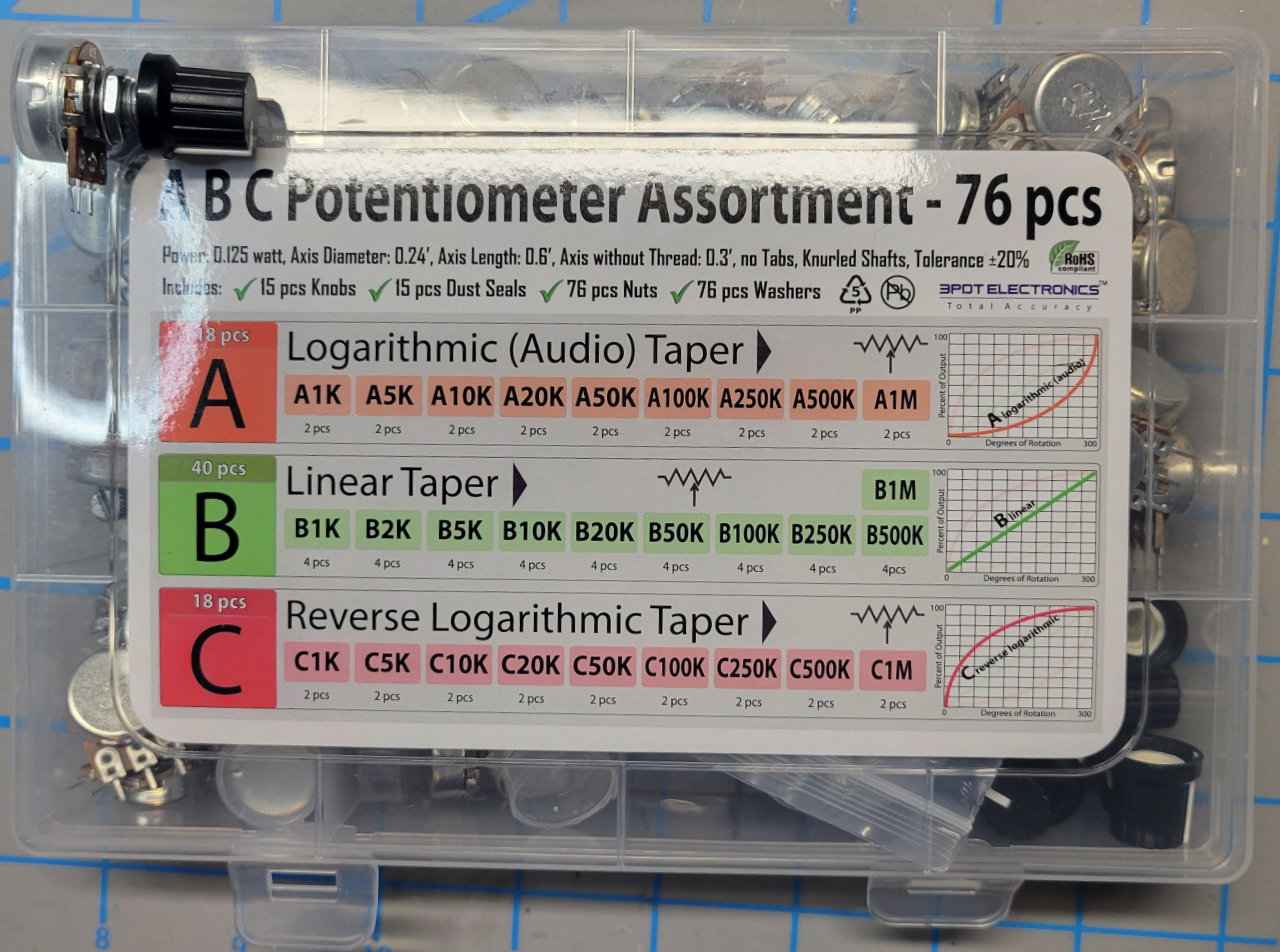
Logarithmic, linear, and reverse log potentiometer assortment
Another type of useful kit is for connectors. Buying individual connectors makes little sense if you plan to use similar connectors in other projects. For the power supply, I bought a kit of screw terminal blocks, a kit for plugging wires into 0.1″ headers, and one for the front panel output jacks in multiple colors, each for less than $10. [2]
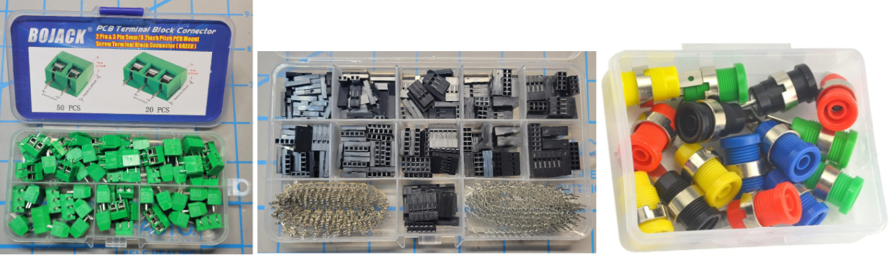
Examples of connector kits
I also bought kits for hardware including a kit of 2mm, 3mm, and 4mm screws with washers and nuts at Microcenter and a kit of #6 screws with washers and nuts.
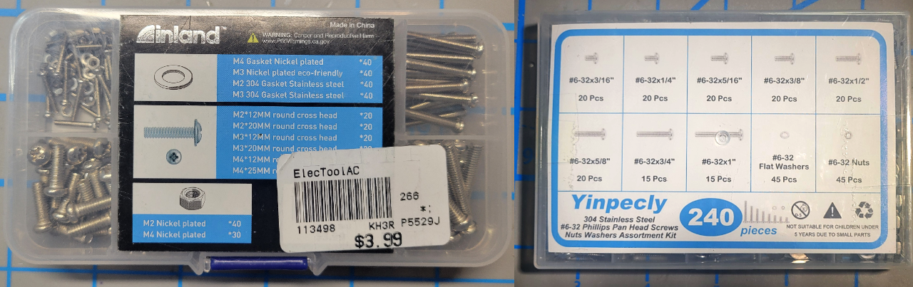
Metric and #6 machine screw kits
I started testing the high-voltage power supply with several 1W resistors in series but I finally broke down a bought a kit of 10W resistors which made testing much easier. I also bought a kit of 34 different 500mW zener values, sure to last me a lifetime. (With semiconductors you could be buying parts that do not meet specifications but I will test them before I use one to make sure they are what they say they are.) I bought a kit of 1W resistors and high-voltage capacitors for the project as well.
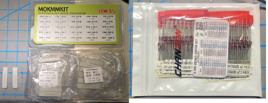
10W power resistor kit and zener diode kit
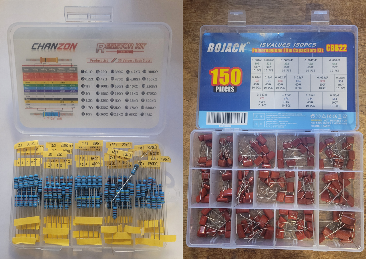
1W resistor and high-voltage capacitor kit
Kits work for simple components such as resistors, hardware, connectors, etc. but not all kits are great. I bought a kit of 10 panel LED lights in different colors for $9 that seemed like a better deal than buying individual lights from Digikey at $4 each. Unfortunately, while the lights in the kit looked like the ones at Digikey, they were poorly made, the crimped-on leads fell off and the LEDs were not glued into the housing so they canted when installed in the panel. I gave up and ordered two of the more expensive ones for my project.
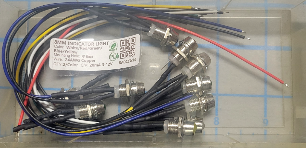
Cheap, poorly made kit of LED panel lights
Similarly, I ordered a set of cord strain reliefs from Amazon but they were sort of inelegant (they would have worked fine) so I bought the more expensive one Paul Horowitz recommended at Digikey.
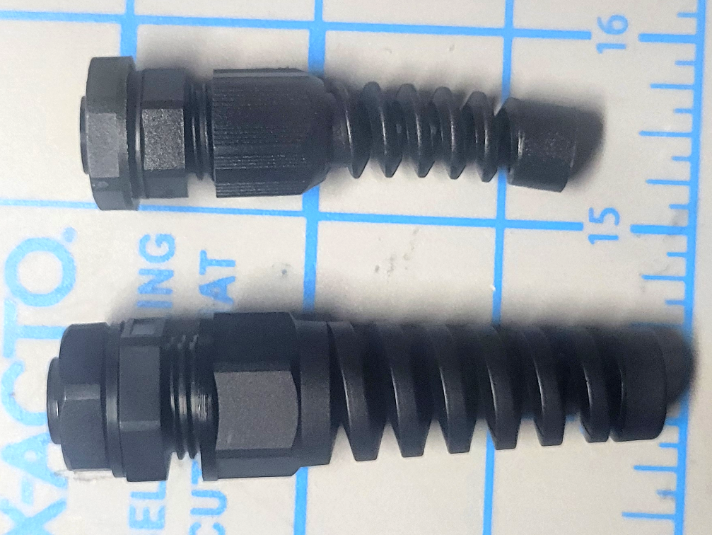
Strain relief cord connectors. I didn’t like the size of the cheaper one on the bottom
Here are some additional kits I bought before the high-voltage power supply project.
The book uses uses 5% resistors with only a few exceptions (e.g., Lab 7L.4) because we want our students to think about component tolerance in their designs. One percent resistors make it too easy to forget that components may not be the exact value printed on them. For that reason I also use 5% resistors in my designs except where a higher precision part is necessary to make the circuit work. I bought this kit of 1% resistors for those occasions. (Obviously there are many more 1% values than contained in this kit but with good design I can usually make one of these values work.)
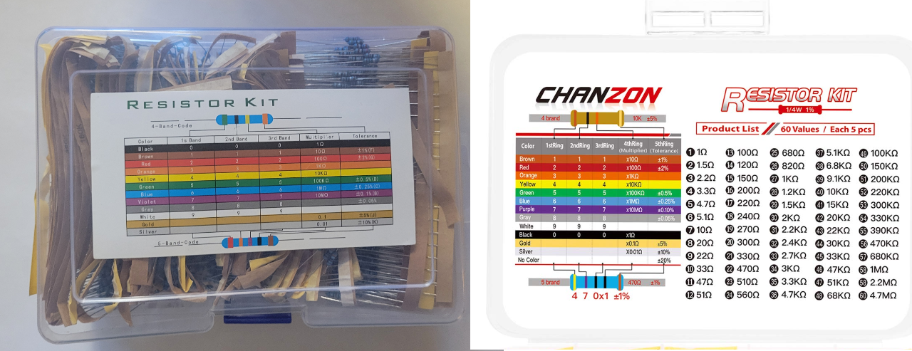
1%, 1/4W resistor kit
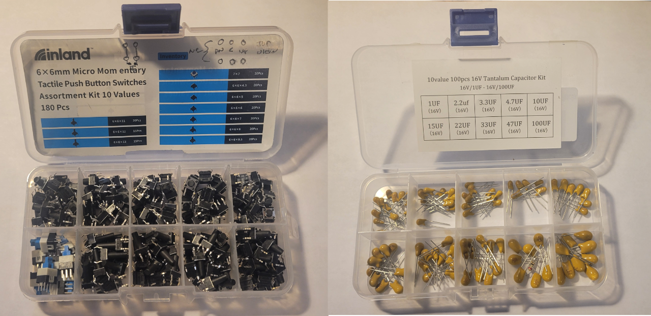
Pushbutton switch and tantalum capacitor kits
[1] The 1N400X series of 1A rectifier diodes comes in increasing max reverse breakdown voltage from 50V for the 1N4001 to 1000V for the 1N4007. A hundred of the 1N4001 costs about $5 while 100 of the 1N4007 costs about $7 so it really doesn’t make sense to stock anything but the 1N4007.
[2] I have mixed feelings about the output banana jack kit. On one hand they look great and allow you to plug in hooded banana plugs like the ones on multimeter leads. This is great for this application which has dangerous voltage on the high-voltage output. The problem is the design makes it hard to solder. The large, thick metal tail takes so long to heat up to get a good solder joint that the plastic housing starts to deform. I destroyed two before I realized you have to plug in a hooded banana jack while you solder to keep the plastic intact until it cools. These would be much better if the solder tail was much narrower so it could heat up quickly to solder. I will probably use a Dremel tool to isolate the tab before using them again.
Read More