
Why not use the new built-in Arduino debugger and Arduino IDE for microcontroller development? (updated)
A reader pointed out that:
“The [the SAMD21 alternative] Arduino Zero not only comes with a preinstalled debug header, it comes with the debug hardware included. There is no additional debug hardware required at all. You can debug directly using the Arduino IDE.
Although more expensive than the other M0+ boards, it turns out cheaper in total as you don’t need the debug hardware.”
Update 2025-09-19: The discussion below concludes that the Arduino Zero used with the Arduino IDE is not a good substitute for the SparkFun SAMD21 Mini used with the J-Link debugger and Seeger’s Embedded Studio. However, if you are willing to deal with the inconvenience of connecting the Arduino Zero to the breadboard, the onboard debugger on the Arduino Zero works with Embedded Studio to do all the microcontroller labs in LAoE and it is a cheaper solution than using the SAMD21 and J-Link. See How to Use an Arduino Zero in Place of the SparkFun SAMD21 in Chapters 22-27
My response:
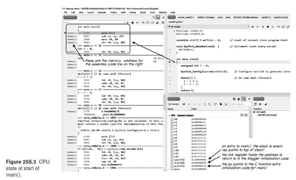
When we created the new microcontroller lessons in summer 2020 the Arduino debugger IDE was not available (except as a beta). We did try it out at the time but had trouble getting it to work. Even now, the Arduino IDE debugger is still somewhat limited – offering only high-level access (at the C code level) and tied to the Arduino ecosphere. It also is limited to a small number of boards without the hardware debugger (it was even fewer then). Also, we prefer (for pedological reasons) to be able to examine disassembled code and raw memory (see Figure 25S.3 in the book – reproduced below). At the time, the J-Link EDU Mini was only $13 (it has gone up significantly to $60 since then) so we did not see it as cost impediment. In our opinion, the Segger debugger is much more representative of modern development/debugging environments and we still feel it provides a better introduction to serious embedded systems development. It also interfaces well with the Segger embOS RTOS, which we believe is one of the two most important contributions in the second half of the new edition of LAoE (the other being finite state machine software and hardware design concepts).
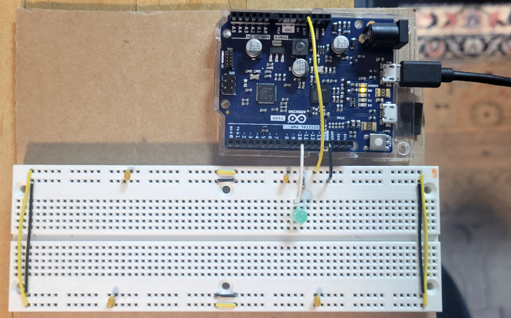
Finally, we want readers to consider a microcontroller just another component in a circuit/product design. The traditional Arduino footprint of the Arduino Zero is not well suited to breadboarding. (See image below.) We only considered breadboard compatible microcontroller boards in developing the book’s embedded systems labs; however, I did include the Arduino Zero in the list of alternatives microcontroller boards in Chapter 22O. See https://laoe.link/LAoE_Chapter_22O.pdf, Section 22O.1.2.2, where we also note that the debug header is included (but it may no longer be populated based on the current images on the Arduino store web site).
That said, our undergraduate course used the Arduino environment because it was an easy and fast way to learn embedded systems. The purpose of this book was to go beyond that into professional development tools, hence the switch to the Segger tool chain.
We did recently try the internal Atmel Embedded Debugger (EDBG) hardware on the Arduino Zero board with the Arduino IDE (Version 2).
We were able to compile and test all the exercises in Lab 22L using the Arduino IDE and the Arduino Zero EDBG. You must remove or comment out the line
#include "samd21.h" // add to use CMSIS
in each program or you will get a compile error.
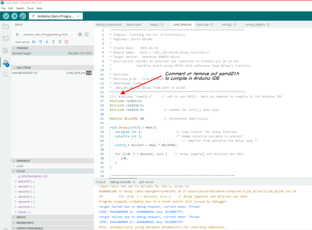
Nevertheless, the Arduino IDE supports CMSIS and all the code compiled and ran. The Arduino IDE runs the SAMD21 at full speed (48Mhz) so you have to slow down the Delay() routine (we changed the DELAYMUL value from 60 to 6000) to see the LED blink.
However, when we tried the Chapter 23 Labs, the programs would not compile because the internal Arduino support code already set the SysTick_Handler() to its own interrupt service routine.
C:\Users\David\AppData\Local\arduino\sketches\35BDD63E14BC04C0ACBA81EB7D1B6C1F/..\..\cores\arduino_samd_arduino_zero_edbg_7ab4d6888def7306e779da082f31f5d6\core.a(cortex_handlers.c.o): In function `SysTick_Handler':
C:\Users\David\AppData\Local\Arduino15\packages\arduino\hardware\samd\1.8.14\cores\arduino/cortex_handlers.c:171: multiple definition of `SysTick_Handler'
C:\Users\David\AppData\Local\arduino\sketches\35BDD63E14BC04C0ACBA81EB7D1B6C1F\sketch\JLink_Blink.ino.cpp.o:D:\Users\David\Documents\Arduino\JLink_Blink/JLink_Blink.ino:37: first defined here
collect2.exe: error: ld returned 1 exit status
exit status 1
Since the embedded system lessons in Learning the Art of Electronics program the SAMD12 “bare metal” (i.e. as though they have control of the entire microcontroller), the lessons in the book conflict with similar code in the Arduino environment. So, tThe Arduino Zero will not work with all the lessons when used in the Arduino IDE environment even though the Arduino IDE does support CMSIS. Looking at the Arduino init() function, Arduino enables all the SERCOM peripherals (SERCOM0 through SERCOM5), the Timer/Counters (TCC0 – TCC2 and TC3 – TC5), and the ADC and DAC, so the book code that tries to use these peripherals is likely to conflict with Arduino code.