
How to Use an Arduino Zero in Place of the SparkFun SAMD21 in Chapters 22-27
At the time we developed the new microcontroller lessons for the second edition of Learning the Art of Electronics, the Segger J-Link EDU debugger had a list price of about $13. (All prices in $US as of 9/2025.) Unfortunately it is now $60 and the SparkFun SAMD21 Mini is an additional $25 for a total of $85. An alternative is the Arduino Zero board at a list price of $48 (but you may find it cheaper — we bought several on eBay for about $14 shipped). The advantage of the Arduino Zero is it has a built in debugger (called EDBG) that works with Segger’s Embedded Studio with no additional hardware (other than a USB cable). The Arduino Zero uses the same model microcontroller as the SAMD21 Mini, the Cortex-M0+ SAMD21G18A, and the Arduino pin numbers on the Zero connect to the same SAMD21 pins as the Arduino pins on the SparkFun board. That means all the code in the microcontroller chapters of LAoE work with the Arduino Zero with no changes. To use the onboard debugger, you connect your development computer to the Arduino Zero Debug USB connector (the one nearest the black external DC power jack — the second USB connector only works with the Arduino IDE).
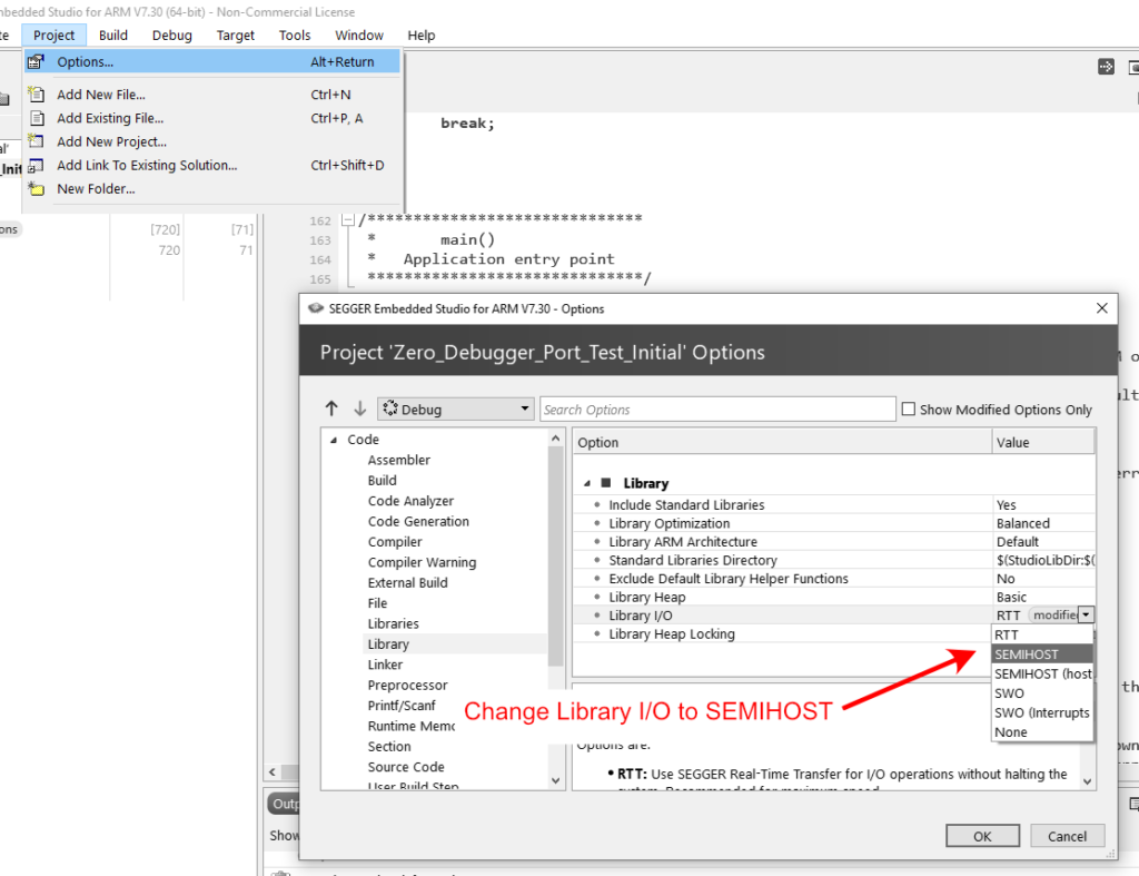
You do need to make one change in Segger Embedded Studio each time you create a new project. Select Project/Options from the main menu then “Library” under the Code heading. Change the Library I/O setting from RTT to SEMIHOST. (This is necessary because the default RTT I/O only supports the J-Link debugger.)
Note: Since Segger IDE overwrites the Arduino loader and libraries, the Arduino Zero will no longer work as an Arduino once you download code to it from Segger Embedded Workshop. You can restore Arduino functionality to the Arduino Zero using the Arduino IDE by following the directions at https://www.arduino.cc/en/Tutorial/ZeroBootloaderUpdate/
The disadvantage of the Arduino Zero is it uses the full-size Arduino Uno form factor and does not plug into a breadboard. The simplest way to use it is to run wires from the Arduino headers to the breadboard. The Arduino Zero may be powered from USB (either connection will work) or from an external 7V to 12V source connected to the DC power jack or Vin pin. You cannot power it from 5V as we do with the SparkFun SAMD Mini. (There is a discussion why below if you are curious.) In the image below, we are powering the Arduino Zero from the USB and using the 3.3V output of the Arduino to power our breadboard devices.
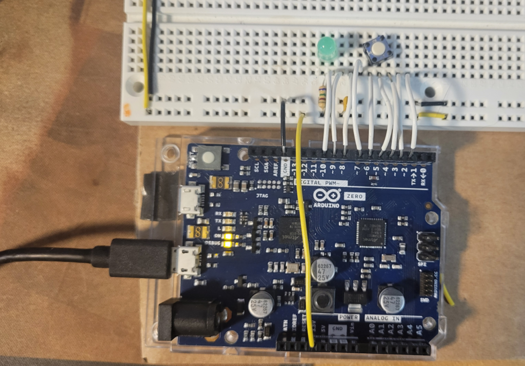
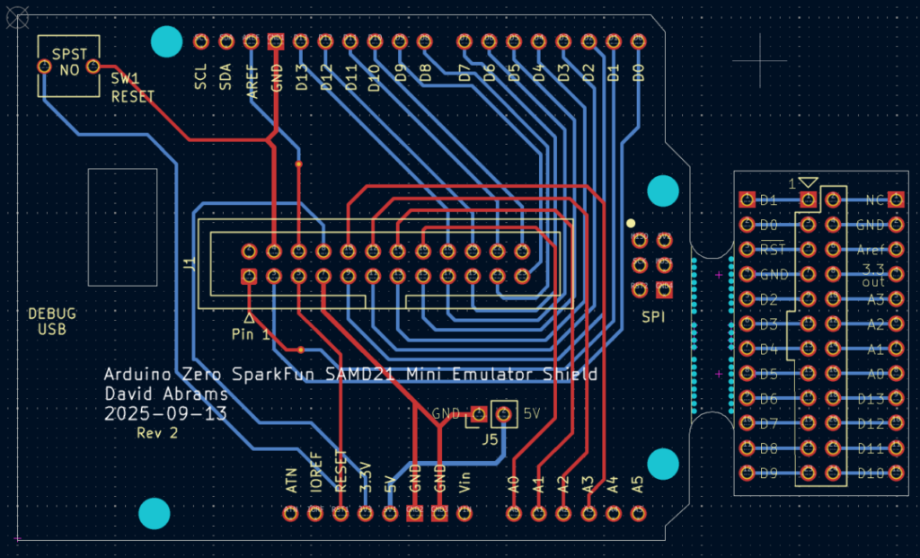
The pin numbers on the Zero board match those on the SparkFun board. However, they are arranged differently so, for example, you cannot plug the matrix keypad of Chapter 23 directly into the Zero headers because there is a gap between Arduino pins 7 and 8. One solution is wire the breadboard to match the SAMD21 Mini as we have done in the image above. Another solution is to build an interface board between the Arduino Zero and the breadboard. In the Arduino ecosystem, boards that mate with the Arduino headers are called “shields.” We prototyped an Arduino shield which connects the Arduino Zero pins common to the SparkFun board to a daughterboard that plugs directly into our breadboard in place of the SparkFun SAMD12 Mini (a SAMD21 emulator).
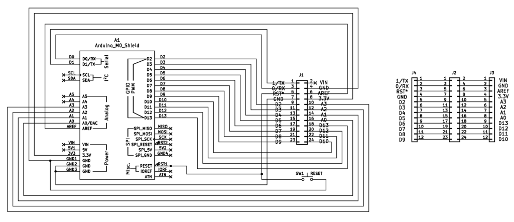
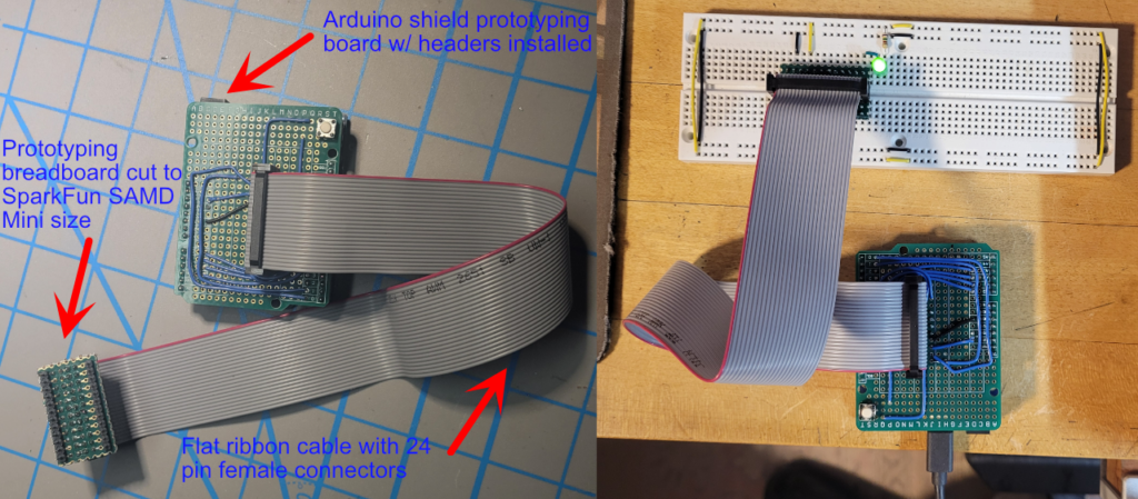
The prototype is built on an Arduino shield prototyping board, using double row headers and a 24-pin flat ribbon cable w/ IDC (insulation-displacement contact ) female connectors to connect the shield to the daughter board, and single row headers to plug the shield into the Arduino Zero and to plug the daughter board into the breadboard. A pushbutton switch parallels the reset button on the Arduino Zero since it is inaccessible under the shield. (The links to parts are what we bought. Many are larger quantities than you need to build a single shield. Adafruit and SparkFun are good sources of these parts in smaller quantities.)
Why is Vin not connected to the daughterboard?
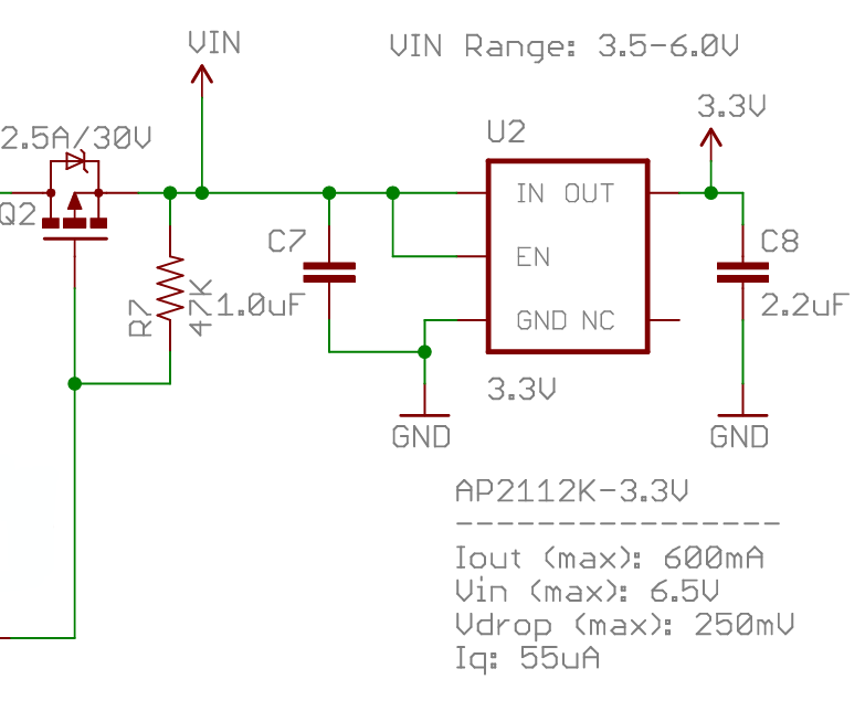
In the book, we connect the Vin pin of the SparkFun board to +5V through a Schottky diode. On the SparkFun board, Vin is connected directly to a low-dropout AP2112K 3.3V voltage regulator which works properly on input voltages from 3.5V to 6.0V. Since the diode drops the +5V input by less than a volt, the voltage regulator has no problem supplying the internal devices with the necessary 3.3V. (When Vin is not supplying power, 5V from the USB connection is supplied to the voltage regulator though MOSFET switch Q2.)
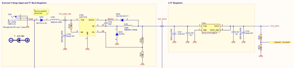
The Arduino Zero, on the other hand, has a much more complicated power scheme. It also uses a low-dropout 3.3V voltage regulator to convert 5V to the power needed by internal devices. However, the +5V comes from one of the two USB connectors or from an external voltage source connected to another voltage regulator. This pre-regulator is a LM2734 high efficiency DC-to-DC switching voltage regulator that converts VEXT or VIN down to 5V. Unlike the LDO voltage regulator, the pre-regulator requires an input voltage of 7V to 12V (either from the Vin pin or the coaxial power jack), it will not work with only a 5V input.
In addition, the Arduino Zero documentation warns: “Supplying voltage via the 5V or 3.3V pins bypasses the regulator, and can damage your board if it is not sufficiently regulated. We don’t advise it.” Therefore, we decided to leave the Vin pin on the daughter board unconnected. This allows the emulator to be plugged into a circuit that has the diode going from 5V to the SparkFun Vin pin with no possibility of damaging anything. It does mean that you must power the Arduino Zero separately, either through one of the USB ports or by applying 7V to 12V DC to the Vin pin or coaxial power jack.
The use of the pre-regulator before the 3.3V regulator means that the latter is lightly stressed (i.e., it experiences low power dissipation since it only drops 1.7V) and allows you to you use the 3.3V regulator on the Arduino Zero to power any of the circuits in the book. In addition, if you need a 5V source, you can run a wire from the 5V pin on the Zero to your breadboard. It is best to keep the combined current draw from these sources to less than 400mA to 500mA. (This is dependent on whether you are powered from the USB or an external supply. The 3.3V regulator is limited to 800mA max.)
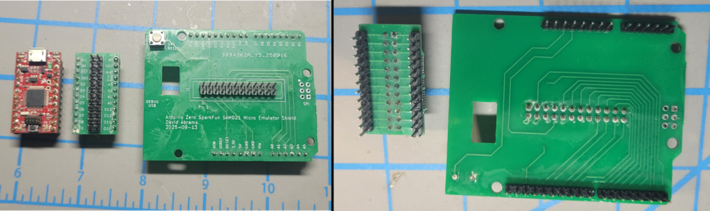
After we tested the emulator on the simple circuits in Chapters 22 and 23, and then on the Lullaby Jukebox of Chapter 27W with no problems, we designed a printed circuit board (PCB) to make assembling the emulator easier. The daughterboard is designed to snap off from the shield. It helps to score it along the cut line of holes on each side with a razor knife before snapping it off. The cutout just to the right of and under the reset switch allows you to see the status LEDs on the Arduino Zero below the shield. The Gerber fabrications files for the Rev 2 emulator board are available below. (Rev 2 added J5 to make it easier to access 5V power on the Arduino Zero if you do not assemble it with stacking headers.)
You can mate the emulator shield to the Arduino Zero with either Arduino stacking headers soldered from the bottom if you still need access to the Arduino I/O pins or use single row, 2.54mm headers soldered from the top of the shield if you don’t. We prefer a 24-pin, 2.54mm male box header for J1, the shield jack that the cable plugs into, since it makes it easy to line up the cable connector with the jack and ensures you insert it correctly as it is keyed to the cable connector. However, you can use a double row, 2.54mm header as well, just be careful to have the red stripe on the ribbon cable go to pin 1 on the emulator board. Both the box header and the double row headers are soldered from the bottom of the shield.
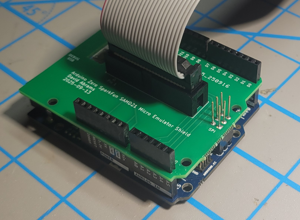
Shield built with Arduino Stacking Headers and Box Header for Cable Connection
Shield and daughterboard built with Single and Double Row Headers
The daughter board requires two sets of 12-pin single row, 2.54mm headers soldered from the top and a single 2×12, 2.54mm double row header soldered from the bottom. See image above. Since this header is not keyed, make sure the red stripe on the ribbon cable goes from pin 1 on the shield to pin 1 on the daughterboard when you plug them together.
An alternative to using connectors at the daughterboard is to use an IDC solder transition (individually available for $2.63 each at Mouser). See image below. The advantages to this are that it is lower profile and that it allows us to shorten the excessively long (in our opinion) 30mm cable we bought on Amazon to connect the shield to the daughterboard. While there are special tools to assemble the IDC connectors, we have been successful putting the pins of the transition in a small breadboard (to protect them), inserting the ribbon cable into the transition, and using a vise to squeeze the cap onto the transition.
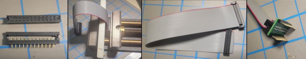
Daughterboard with soldered 24-pin ribbon cable to PCB transition connector
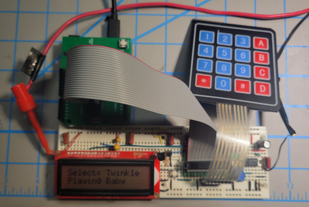
Emulator running the Lullaby Jukebox
Here are the Gerber files that can be sent to a PCB manufacturing house to fabricate the emulator shield printed circuit board:
Arduino Zero SAMD21 Mini Emulator Shield Gerbers Rev 2
We have a small number of extra blank Emulator PCBs. They are $USD10 each. If you are interested, send a request to parts@LAoE.link