
General Errata
Errata other than A0E cross reference corrections and changes to the FPGA and microcontroller installation instructions.
Note: You can sort by page or by date, and you can print the list or download a pdf. Errata are corrected in successive printings, with approximate cutoff dates where applicable; so you can scroll down a date-sorted list to find needed corrections.
| Page | Location | Description | Found By | Date |
|---|---|---|---|---|
| 541 | Figure 12L.18 | The caption should read "At low VDS, JFET I-V behavior approximates that of a resistor. | We found it ourselves | 20250303 |
| 5 | Footnote 3 | Should read "... to produce ever more efficient ..." | Jeff Stribling | 20250417 |
| 461 | Figure 10L.3 | The upper (NPN) BJT is a MJE3055 and the lower (PNP) is a MJE2955 | We found it ourselves | 20250728 |
| 500 | Figure 11L.8 | The SCR part number is MCR218-4G (but the last digit "4" is the voltage and the "2" and "8" parts are fine - actually almost any SCR will work for this lab) | We found it ourselves | 20250728 |
| 1148 | Index | "VP01" should be "VP0106" | We found it ourselves | 20250728 |
| 1141 | Index | The IRLIB9343 MOSFET is no longer used in the book. Please ignore this index entry. | We found it ourselves | 20250728 |
| 33 | Figure 1L.10 | The figure shown is incorrect. Here is the correct figure: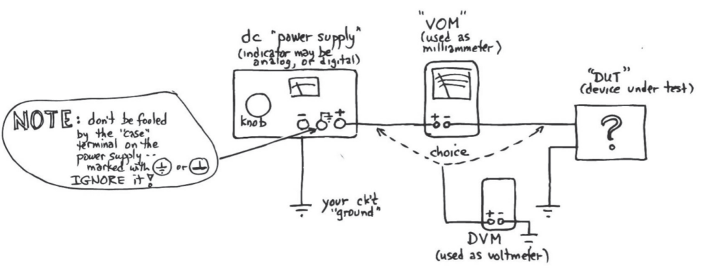 | Florian Mintgen | 20250731 |
| 556 | Figure 13N.3(a) | The pinout for the TSTS7100 IR LED is reversed. The anode is nearest the tab, Here is the correct figure: 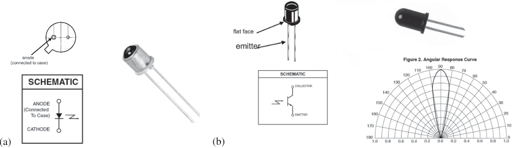 | Kathryn Ledbetter | 20251015 |
| 558 | §13L.2.1 | The input impedance on the LMC555's control input is 66k (not 33k). | Kathryn Ledbetter | 20251015 |