
General Errata
Errata other than A0E cross reference corrections and changes to the FPGA and microcontroller installation instructions.
Note: You can sort by page or by date, and you can print the list or download a pdf. Errata are corrected in successive printings, with approximate cutoff dates where applicable; so you can scroll down a date-sorted list to find needed corrections.
| Page | Location | Description | Found By | Date |
|---|---|---|---|---|
| 541 | Figure 12L.18 | The caption should read "At low VDS, JFET I-V behavior approximates that of a resistor. | We found it ourselves | 20250303 |
| 5 | Footnote 3 | Should read "... to produce ever more efficient ..." | Jeff Stribling | 20250417 |
| 461 | Figure 10L.3 | The upper (NPN) BJT is a MJE3055 and the lower (PNP) is a MJE2955 | We found it ourselves | 20250728 |
| 500 | Figure 11L.8 | The SCR part number is MCR218-4G (but the last digit "4" is the voltage and the "2" and "8" parts are fine - actually almost any SCR will work for this lab) | We found it ourselves | 20250728 |
| 1148 | Index | "VP01" should be "VP0106" | We found it ourselves | 20250728 |
| 1141 | Index | The IRLIB9343 MOSFET is no longer used in the book. Please ignore this index entry. | We found it ourselves | 20250728 |
| 33 | Figure 1L.10 | The figure shown is incorrect. Here is the correct figure: | Florian Mintgen | 20250731 |
| 556 | Figure 13N.3(a) | The pinout for the TSTS7100 IR LED is reversed. The anode is nearest the tab, Here is the correct figure: 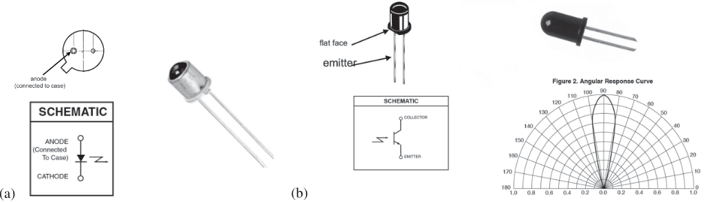 | Kathryn Ledbetter | 20251015 |
| 558 | §13L.2.1 | The input impedance on the LMC555's control input is 66k (not 33k). | Kathryn Ledbetter | 20251015 |
| 0 | https://www.digikey.com/en/resources/edu/harvard-lab-kit | The kit lists on this DigiKey site are for the first edition only. The digital kit in particular is very different in the 2nd Edition of LAoE. We are trying to get Digikey to add a note to this effect. | Tyler Arrigoni | 20260519 |