
Why not use the new built-in Arduino debugger and Arduino IDE for microcontroller development? (updated)
A reader pointed out that:
“The [the SAMD21 alternative] Arduino Zero not only comes with a preinstalled debug header, it comes with the debug hardware included. There is no additional debug hardware required at all. You can debug directly using the Arduino IDE.
Although more expensive than the other M0+ boards, it turns out cheaper in total as you don’t need the debug hardware.”
Update 2025-09-19: The discussion below concludes that the Arduino Zero used with the Arduino IDE is not a good substitute for the SparkFun SAMD21 Mini used with the J-Link debugger and Seeger’s Embedded Studio. However, if you are willing to deal with the inconvenience of connecting the Arduino Zero to the breadboard, the onboard debugger on the Arduino Zero works with Embedded Studio to do all the microcontroller labs in LAoE and it is a cheaper solution than using the SAMD21 and J-Link. See How to Use an Arduino Zero in Place of the SparkFun SAMD21 in Chapters 22-27
My response:
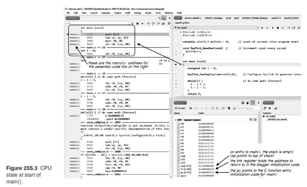
When we created the new microcontroller lessons in summer 2020 the Arduino debugger IDE was not available (except as a beta). We did try it out at the time but had trouble getting it to work. Even now, the Arduino IDE debugger is still somewhat limited – offering only high-level access (at the C code level) and tied to the Arduino ecosphere. It also is limited to a small number of boards without the hardware debugger (it was even fewer then). Also, we prefer (for pedological reasons) to be able to examine disassembled code and raw memory (see Figure 25S.3 in the book – reproduced below). At the time, the J-Link EDU Mini was only $13 (it has gone up significantly to $60 since then) so we did not see it as cost impediment. In our opinion, the Segger debugger is much more representative of modern development/debugging environments and we still feel it provides a better introduction to serious embedded systems development. It also interfaces well with the Segger embOS RTOS, which we believe is one of the two most important contributions in the second half of the new edition of LAoE (the other being finite state machine software and hardware design concepts).
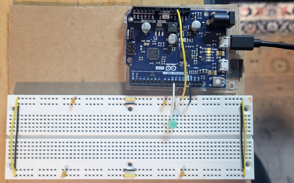
Finally, we want readers to consider a microcontroller just another component in a circuit/product design. The traditional Arduino footprint of the Arduino Zero is not well suited to breadboarding. (See image below.) We only considered breadboard compatible microcontroller boards in developing the book’s embedded systems labs; however, I did include the Arduino Zero in the list of alternatives microcontroller boards in Chapter 22O. See https://laoe.link/LAoE_Chapter_22O.pdf, Section 22O.1.2.2, where we also note that the debug header is included (but it may no longer be populated based on the current images on the Arduino store web site).
That said, our undergraduate course used the Arduino environment because it was an easy and fast way to learn embedded systems. The purpose of this book was to go beyond that into professional development tools, hence the switch to the Segger tool chain.
We did recently try the internal Atmel Embedded Debugger (EDBG) hardware on the Arduino Zero board with the Arduino IDE (Version 2).
We were able to compile and test all the exercises in Lab 22L using the Arduino IDE and the Arduino Zero EDBG. You must remove or comment out the line
#include "samd21.h" // add to use CMSIS
in each program or you will get a compile error.
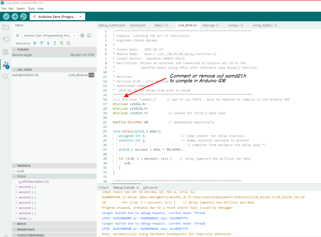
Nevertheless, the Arduino IDE supports CMSIS and all the code compiled and ran. The Arduino IDE runs the SAMD21 at full speed (48Mhz) so you have to slow down the Delay() routine (we changed the DELAYMUL value from 60 to 6000) to see the LED blink.
However, when we tried the Chapter 23 Labs, the programs would not compile because the internal Arduino support code already set the SysTick_Handler() to its own interrupt service routine.
C:\Users\David\AppData\Local\arduino\sketches\35BDD63E14BC04C0ACBA81EB7D1B6C1F/..\..\cores\arduino_samd_arduino_zero_edbg_7ab4d6888def7306e779da082f31f5d6\core.a(cortex_handlers.c.o): In function `SysTick_Handler':
C:\Users\David\AppData\Local\Arduino15\packages\arduino\hardware\samd\1.8.14\cores\arduino/cortex_handlers.c:171: multiple definition of `SysTick_Handler'
C:\Users\David\AppData\Local\arduino\sketches\35BDD63E14BC04C0ACBA81EB7D1B6C1F\sketch\JLink_Blink.ino.cpp.o:D:\Users\David\Documents\Arduino\JLink_Blink/JLink_Blink.ino:37: first defined here
collect2.exe: error: ld returned 1 exit status
exit status 1
Since the embedded system lessons in Learning the Art of Electronics program the SAMD12 “bare metal” (i.e. as though they have control of the entire microcontroller), the lessons in the book conflict with similar code in the Arduino environment. So, tThe Arduino Zero will not work with all the lessons when used in the Arduino IDE environment even though the Arduino IDE does support CMSIS. Looking at the Arduino init() function, Arduino enables all the SERCOM peripherals (SERCOM0 through SERCOM5), the Timer/Counters (TCC0 – TCC2 and TC3 – TC5), and the ADC and DAC, so the book code that tries to use these peripherals is likely to conflict with Arduino code.
Read MoreHow many do I buy of Parts List items without a quantity specified?
A reader asked “I uploaded the BOM [Bill of Materials, i.e., the Parts List] to DigiKey. For the parts where no quantity is specified, does that mean any amount between QTY 1 and QTY10 works? I see a considerable price drop when QTY10 are ordered, but I am not sure I need too many left-over parts considering that I am not planning to specialize in analog circuits (of course, that thought may change as I complete the labs).
My response: Many of the resistors and capacitors in the parts lists do not have a value specified in the “Qty Needed” column because we aren’t really sure how many you need and we expect you to buy a kit of resistors and capacitors, not purchase individual values. This is because in some cases it either does not matter much which value you use (for example, pull up resistors in the digital labs) and in others you choose the value based on what works in the circuit. For example, in the filter circuits and the LM555 oscillator, you can use [almost] any resistor and capacitor value that gives you the correct time constant. So a 1k resistor and 100nF capacitor should work as well as a 10k resistor and 10nF capacitor (both result in an R * C time constant of 100uS).
With only the exception where we have specified a quantity of a particular part, we assume you will purchase a kit of most popular values, which usually includes at least 10 of each value – more than enough for the experiments in the book. (The 100uF polymer capacitor used in the switching power supply is a special low ESR [Equivalent Series Resistance] part so it has a quantity but the rest of the capacitors are pretty much generic so do not have quantity specified — but you could use a generic part in the switcher lab and still get an understanding of how switching voltage regulators work, you would just lose some efficiency.) Most of these types of parts make no sense to buy in single quantities – they are too expensive – but a quantity purchase makes little sense for an individual user. A kit is much more economical than buying individual parts for individual use. OTOH, someone stocking a university lab may prefer to buy the values listed at the quantity pricing which is why we have specified particular part numbers – but in reality, there are dozens of other parts numbers for each of the parts we list that would work as well.
Read MoreA reader was confused by the units in the power problem of 1W.2
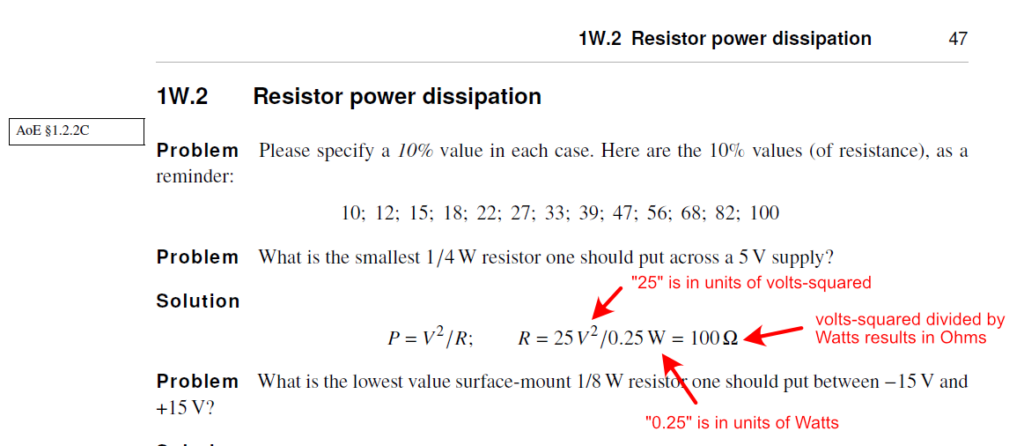
A reader writes “On Page 47, we’re asked to calculate the smallest 1/4W resistor to be put across a 5V supply. The solution gives P=V^2/R which is correct, but the formula after says R=25^2/0.25 which gives an answer of 2k5 ohms. Not the actual answer which should be R=5^2/0.25=100 ohms.”
I responded:
I see why you are confused but the “V2” in the formula in the solution are the units for the value “25.” The “V” in the units is squared but the “25” has already been squared (5 V* 5V = 25 V*V=25 V2).
Since this example occurs early in the book, we are trying to show how electrical units relate to each other and we want to encourage students to include the units with values in their calculations.
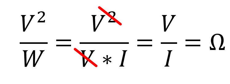
In teaching this stuff we find students often do not carry units though their work and they miss obvious mistakes as a result. (For example, had this calculation used “5V,” the result would have been inverse amps, not Ohms, but if we had written just “5” without the units the mistake would have been less obvious).
Checking units is an easy way to catch errors, particularly when one is still unfamiliar with a subject (although even with years of experience I still include units in my calculations as a check against a mistake). It is too bad we don’t have a symbol for volts-squared, since that would have avoided the confusion.
Read MoreSomeone asked about N.O. and N.C. contacts on a microswitch
A watcher of my 16N.1.3 Debouncing a Switch with a Set Reset Flip Flop video was confused by the switch having both Normally Open (N.O.) and Normally Closed (N.C.) contacts. He was used to pushbutton switches which are usually only N.O. Indeed, most pushbutton switches are Single Pole, Single Throw (SPST) with two contacts and a shorting bar that is held open by a spring so the contacts are open circuit, and then the contacts are shorted together when the user presses the pushbutton. (There are N.C. pushbutton switches and pushbuttons with multiple contacts, either SPDT or DPST but they are less common.)
Microswitches (miniature snap-action switches), on the other hand, are usually (almost always?) SPDT with a common terminal and both a N.O. terminal and a N.C. terminal. See Figure 16L.6 in LAoE or watch the video referenced in Footnote 7 on that page that has a visualization of how a microswitch works and shows the reason we use it for the switch bounce demonstration.
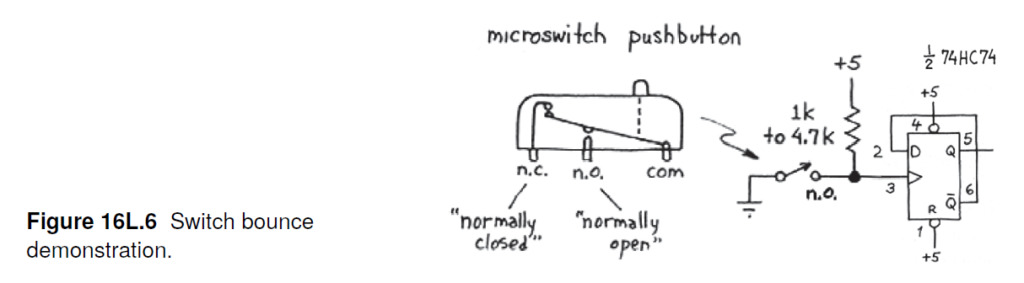
Microswitches often include a lever arm to reduce the actuation force and are typically used as mechanical limit switches; they are rarely human actuated like a SPST pushbutton switch.
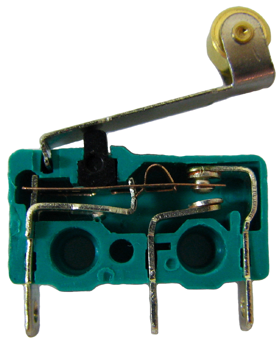 Image courtesy of Benjamin D. Esham
The SPST microswitches that I have seen are actually SPDT switches with the N.C. terminal missing or cut off.
See https://en.wikipedia.org/wiki/Miniature_snap-action_switch for more information.
Read MoreIs there a Harvard course based on the book that I can take?
A reader asked: “What is the name of the summer course? When is the summer course? How many hours is the course – cost? Is it too late to sign up.”
Unfortunately, the only way to take the course based on Learning the Art of Electronics at Harvard is to be enrolled as a student. (The course is also taught in some form at University of Maryland and possibly at Stanford University in the EE Makerspace).
The course used to be taught by me in-person in Cambridge, MA, as a seven-week summer session by Harvard Summer School
and during the term, also in-person, by someone else in the Harvard Extension School
https://extension.harvard.edu/academics/programs/take-a-course/#courses-designed-for-impact
I stopped teaching summer school in 2017 and as far as I know it is no longer available in the summer program. I believe the person teaching it during the term as an evening class stopped when the school insisted he could only teach it remotely. (As you can imagine it is not a course that lends itself to remote teaching – although I did teach it for two terms remotely during COVID as a normal Harvard course, but only the digital portion of the book).
Harvard’s PHYS S-12, taught by Nathan Melenbrink and available in the Summer and Extension School covers some simple electronics in addition to 3-D printing, laser cutting and other fabrication techniques. It is not based on our book but is a fun course to take if you live nearby.
You might want to check your local community college or adult education to see what they offer. Also, in the current world there are a huge number of online resources including videos that could help you tackle it on your own.
Finally, I just gave my step-nephews an Arduino and a Raspberry Pi for their birthdays. Both (but particularly the Arduino when paired with the https://store.arduino.cc/products/arduino-sensor-kit-base) is a fun and easy way to get into embedded computer programming.
Read More
Can you recommend any all-in-one test equipment?
A reader asks:
“I’d like to know if you guys can suggest a good mini lab kit to give me the capability of a freq gen, a oscilloscope, a digital signal monitor, a power supply . all in one. I’ve seen this devices used in university courses used in engineering schools.”
My response:
The one I am familiar with is the Digilent Discovery
https://digilent.com/shop/analog-discovery-3/
https://digilent.com/shop/analog-discovery-3-pro-bundle/
which runs about $380 to $410.
It uses a computer for control and display through USB.
It includes a (approx.) 25Mhz scope, a variable +/- 0.5 to +/-5V power supply (at 800mA max), and a dual channel 12Mhz waveform generator at up to +/-5V.
I am not a great fan of these because of the limited range of the function generator and power supply and the need to use a computer for control but Harvard did send them to students for home use in their undergraduate lab course during the time we were remote because of COVID.
You can find the earlier version (analog discovery 2) on eBay for somewhat less. I have attached an evaluation of Digilent’s openscope product I looked at in 2020 when I was trying to find something to send to students who had to work remotely. It is similar to the analog discovery product.
Digilent has a new product with an included scope, function generator, multimeter, power supply breadboard that looks much more capable (variable up to +/-15V power supply) coming out in June but there is no pricing on it yet:
https://digilent.com/shop/adsmax/
My guess is it will be more expensive than the analog discovery 3.
For my classes taught during COVID, I sent students a 20Mhz two-channel picoscope – https://www.picotech.com/oscilloscope/2000/picoscope-2000-overview (again controlled through USB). It includes a function generator as well but it is limited to an output of +/-2V. The price has gone up enough since then that the low-cost scopes in my oscilloscope post are probably better choices.
I did find this on Amazon:
https://www.amazon.com/Oscilloscope-Plus-Function-Generator-Rechargeble/dp/B09SSC5ZKP
It has a built-in display but again is quite limited. The power supply is +/-5V and 3.3V fixed and there is no specification on current output capability, scope bandwidth or function generator output range.
I am not sure what you plan to use this equipment for (the experiments in our book?) or what your budget is but personally, I would recommend scouring eBay for more capable used equipment. I bought three of my favorite HP triple-output power supplies for about $150 and sold one to a friend for $50. I bought an older, higher output triple-output supply for $50 on eBay as well. As long as you are willing to wait, in my experience eBay often has some bargains. My function generator was a closeout at about $170 and is very capable. (However, I did talk my wife into giving me a very nice oscilloscope as a birthday present <g>.)
You can buy what looks like a reasonable oscilloscope for about $180 new (see my comments at https://learningtheartofelectronics.com/a-reader-asked-about-oscilloscopes/ ) . The FNIRSI has a built in 2MHz (10Mhz for sine waves) function generator (but the specifications do not say what the output range is.)
2025-06-01 Update
Analog Devices also has an all-in-one USB connected device, the ADALM2000 Advanced Active Learning Module. It includes a two-channel 25Mhz oscilloscope, a 30MHz function generator, a logic analyzer, and a +/- 0 to 5V @50mA power supply for about $232. The function generator is limited to +/-5V output. A $38 power booster board provides +/- 0 to 5V supplies at 400mA or – 1.5V to -15V and +1.5 to +15V power outputs at 700mA. (Interestingly , the power booster appears to be open source, the Analog Device page for it includes schematics and Gerber PCB files.) Again, these types of devices seem limited to me and you are dependent on the vendor for the PC software.
Read More